Uncrewed Aerial Systems (UAS)
2021 - 2022: AVIATA Mechanical Airframe Co-lead
2020 - 2021: AVIATA Mechanical Airframe Engineer
Overview
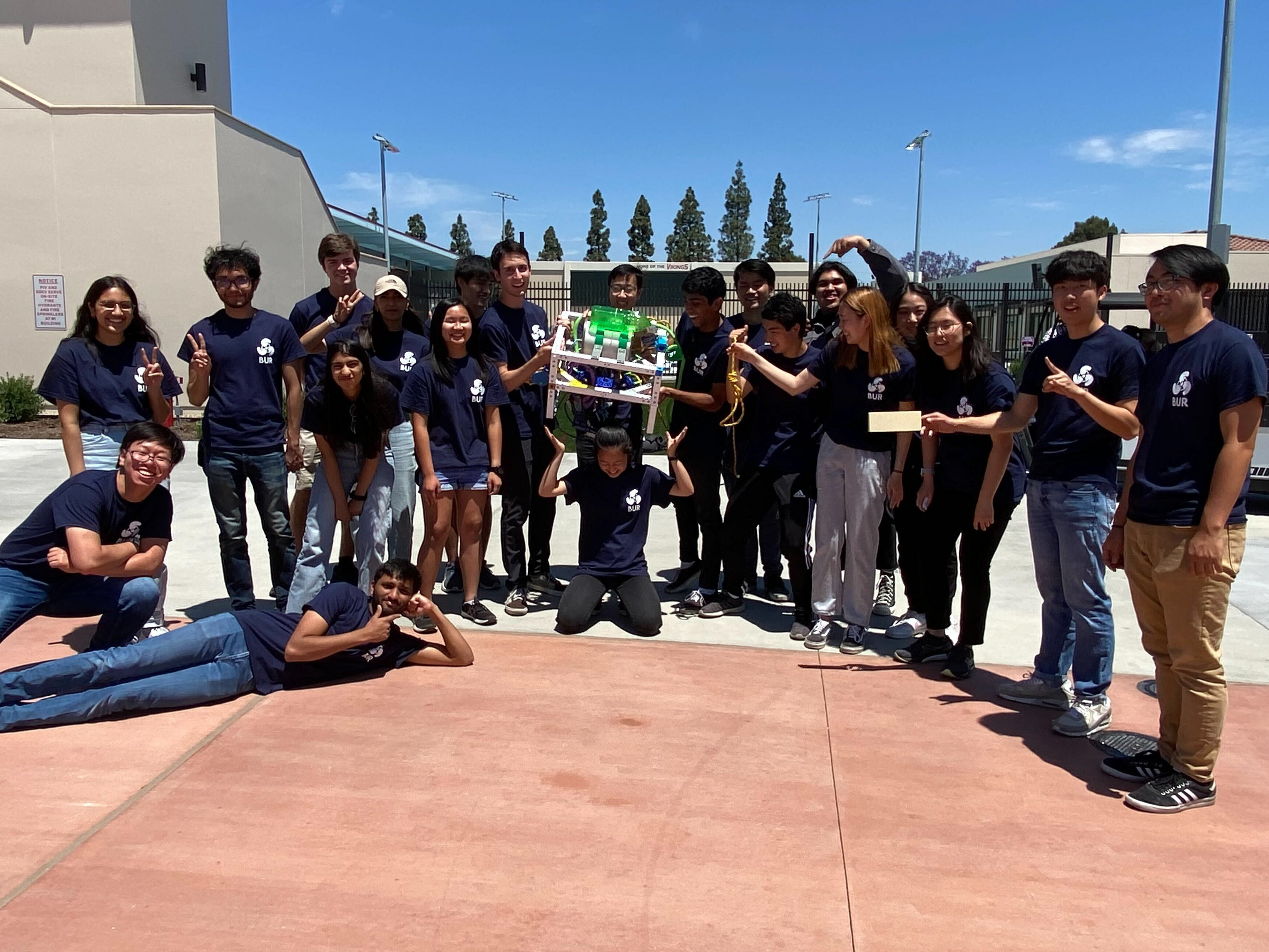
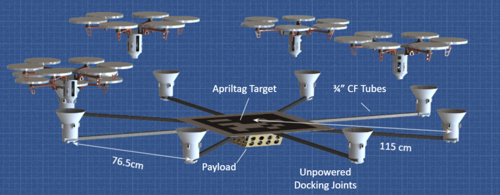
Our 15-person team participated in NASA's Undergraduate Student Research Challenge (USRC). Our research concept is called Autonomous Vehicle Infinite Air Time Apparatus (AVIATA). Its goal is to create an autonomous infinite flight system using a network of 10 DJI F550 drones. In theory, each drone can dock to the payload structure and detach to recharge at separate intervals. This technology may significantly improve flight time of drones, leading to expanding real-life applications in first responder teams, aerial delivery, and more. Our team prototyped and tested this concept.
Objectives
Several key objectives are assigned to the Mechanical Airframe Team:
- Develop and test the docking mechanism hardware while collaborating with the software from the Computer Vision Team and the Docking teams. The mechanism shall be structurally stable in expected flight loads and be flexible to accommodate for small errors in the docking procedure.
- Design and implement the payload mechanism capable of easily holding 2kg while creating minimal stability issues for the Controls Team.
- Deliver relevant estimated assembly statistics to the Controls Team for autonomous flight stability.
Skills
Mechanical Design: SolidWorks, design for manufacturing
Prototyping: 3D Printing, test procedure development, data analysis and reporting, component testing
Machine Tools: Hand tools, fasteners, sanders
Management: Task Delegation, Gantt Chart
Key Tasks
As a position on this team, my key tasks involved not only technical roles across various systems, but also administratively planning the event logistics. This included the following tasks:
Octocopter-like Frame Configuration
Configuration Selection:
- Conducted trade study to select the overall configuration of the system: an octocopter-like frame. Compared to its alternative (an octagon-shaped frame), the octocopter frame offered lighter weight, ease of mounting vision tags, and easily defined static arms. However, each arm would need to withstand higher expected loads.
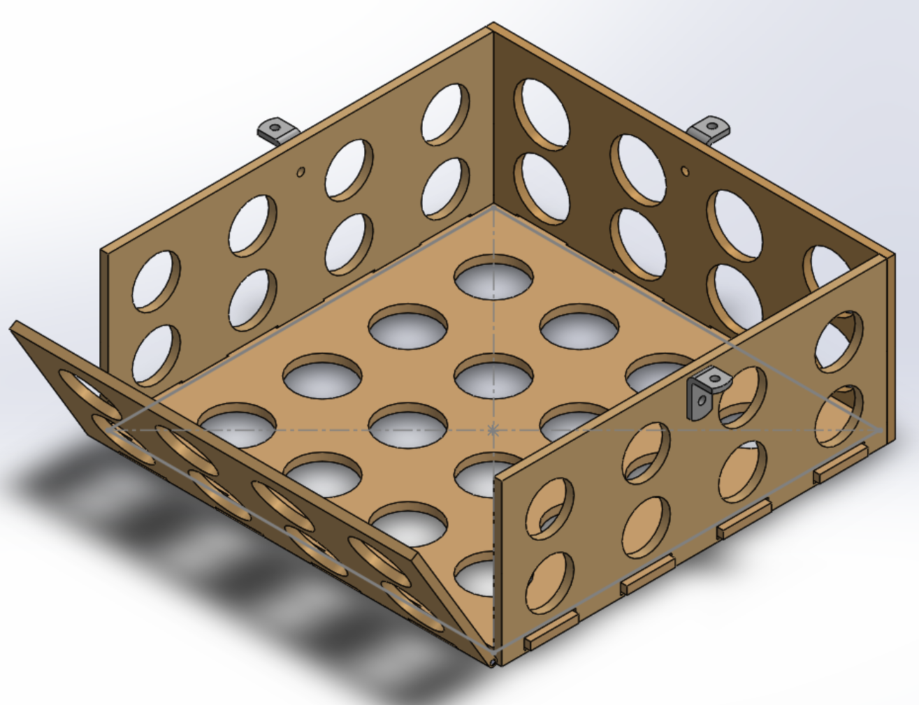
Final Payload Bay
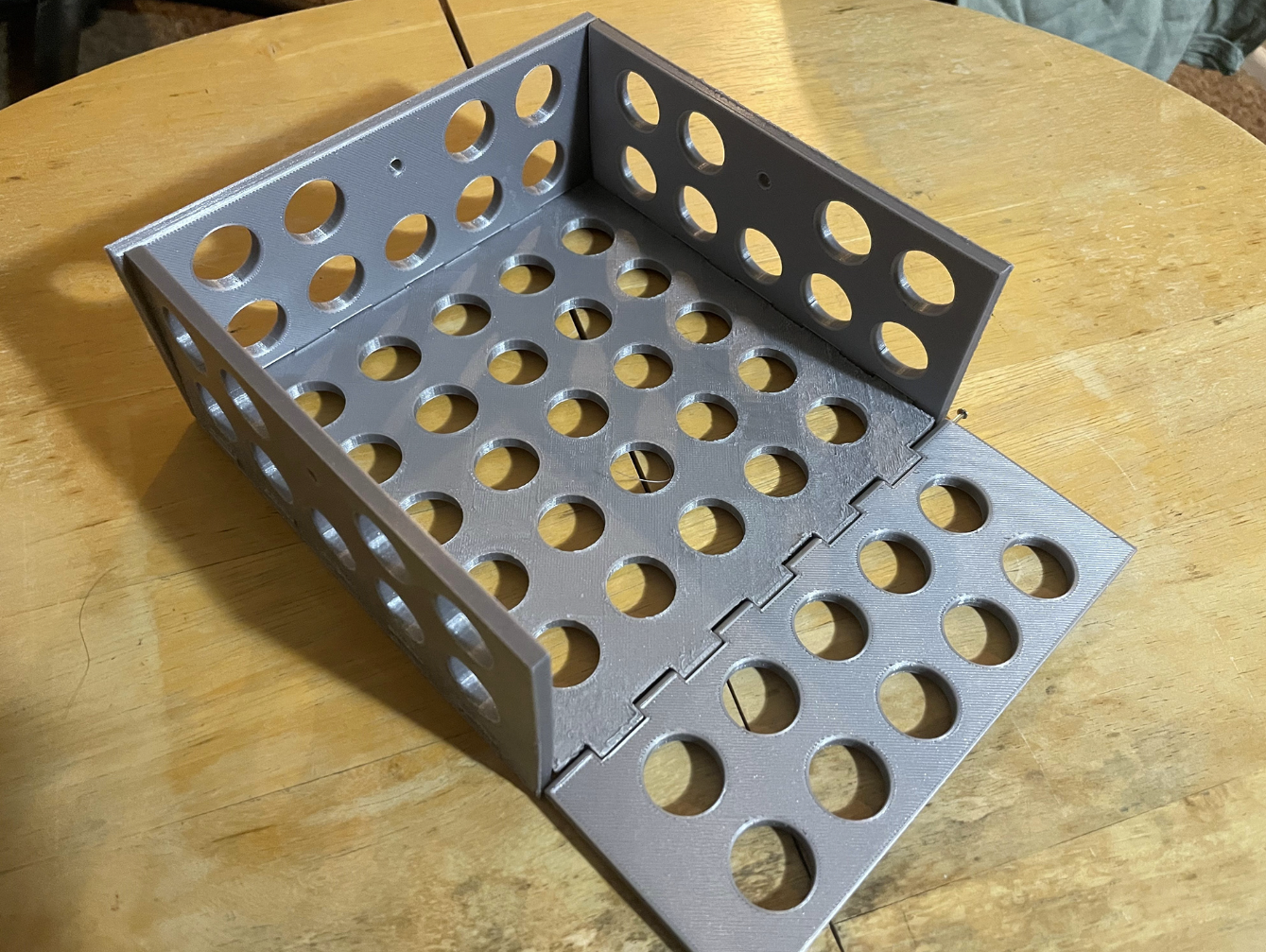
Printed Payload Bay
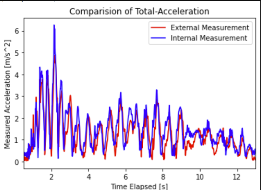
Vibration Test Results
Payload Bay Design:
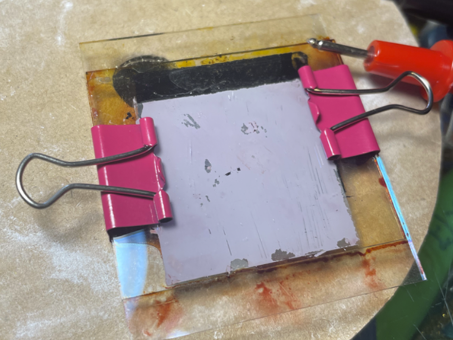
- Selected and tested the payload attachment system to minimize in-flight center-of-gravity shifts. If the payload moves or swings around, large controls adjustments may be necessary. I designed a 16x16x6 cm payload box close to the central frame horizontally and vertically. By having payload close to the center-of-gravity, the moment arm is reduced, making in-flight compensations easier.
- In testing, I 3D printed the payload box and loaded it with 2kg. Phone accelerometers both inside and outside the box collect acceleration over time. The two accelerations are plotted and overlayed in Google Collaboratory using Python, and they show no significant acceleration lag. This means that there would be minimal payload oscillatory response to sudden external acceleration.
Isometric View
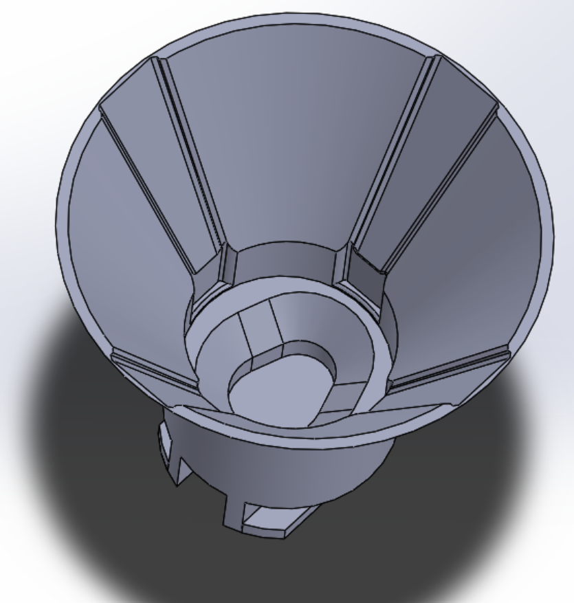
Guide Rails, Cylindrical Lock, Egg Orientation Guide
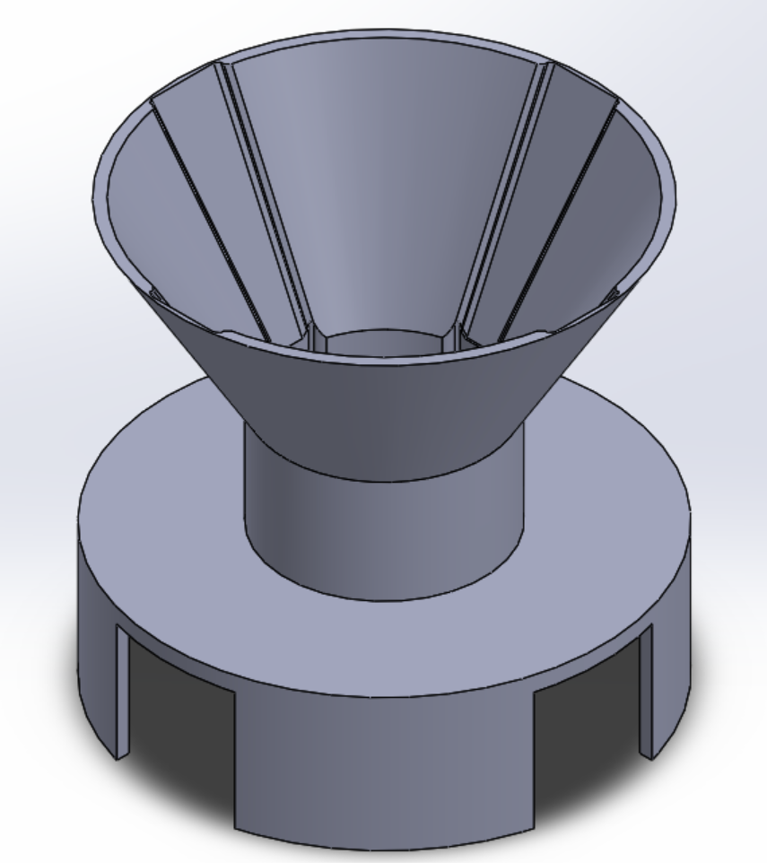
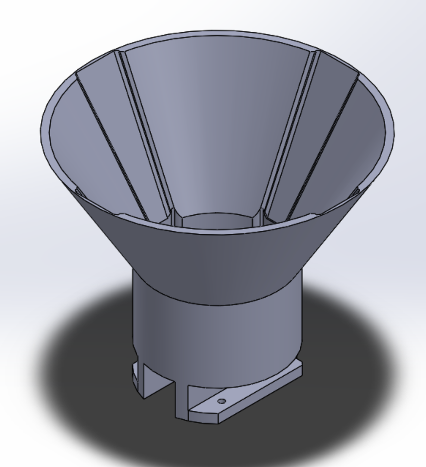
Docking Guide Cone (Test Version)
Docking Cone Design:
- Designed and developed a docking guide cone that allowed successful docking at up to 30 degree misalignment between the drone and the docking port.
- Created conical opening with guide rails to assist in approach, a cylindrical locking mechanism to secure docking, and an egg-shaped key to ensure correct orientation.
- Iteratively tested the 3D-printed design with the Docking Team and the Controls Team.
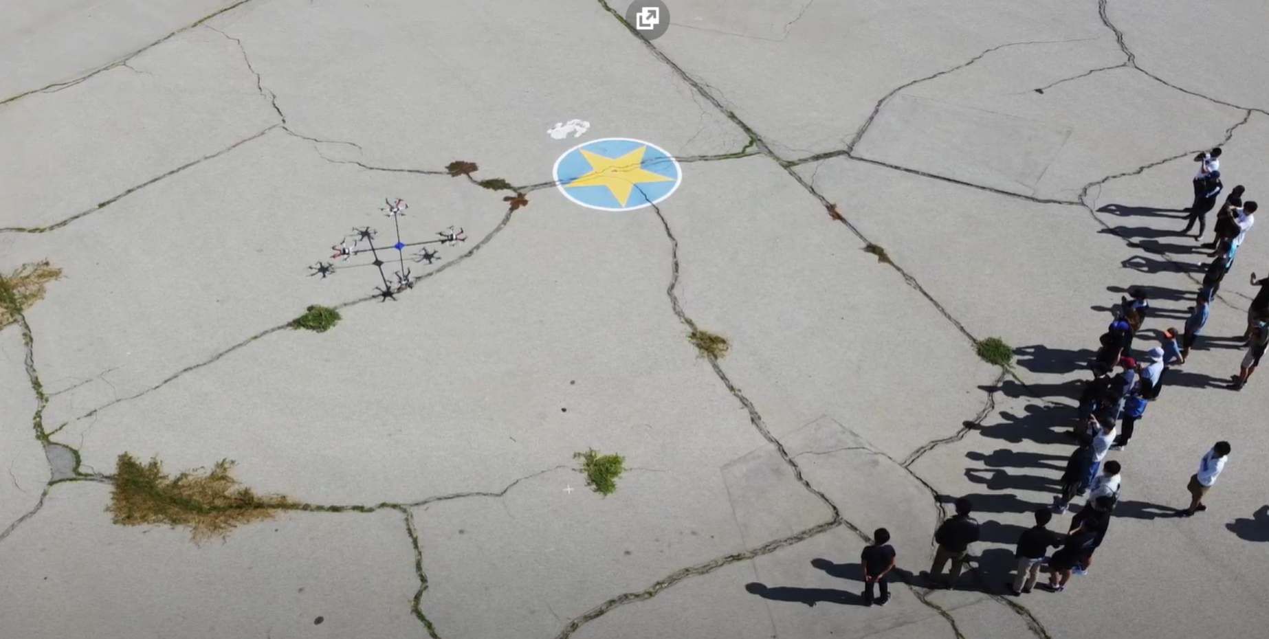
4-Drone Test Top View
4-Drone Test
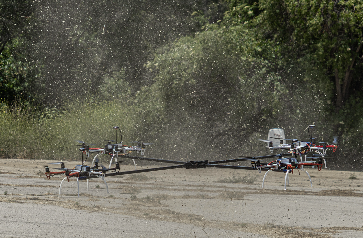
4-Drone Test in Progress
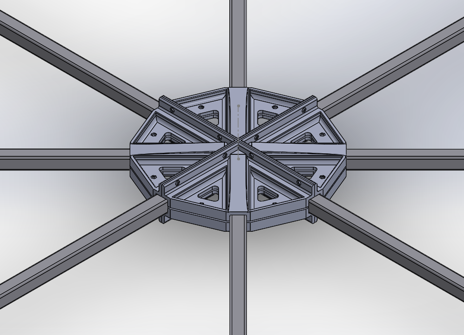
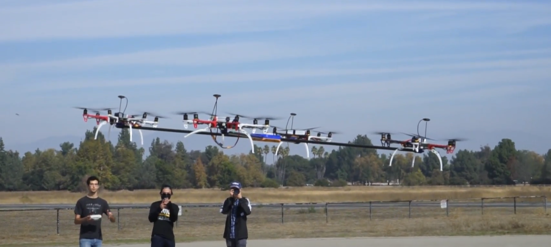
8-Drone Test central frame
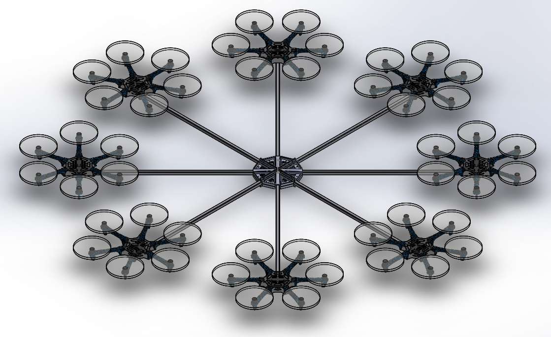
8-Drone Test assembly
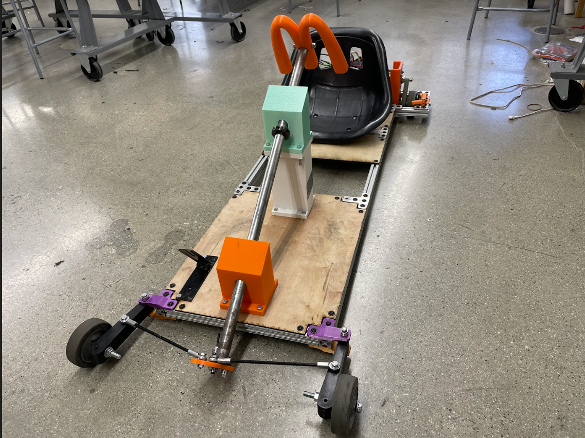
4-Drone and 8-Drone Testing:
- Designed and manufactured special 3D-printed frames to specifically test stability of autonomous controls system.
- Broke down large assemblies to fit the size of available printers.
- Delivered system statistics to the Controls Team.
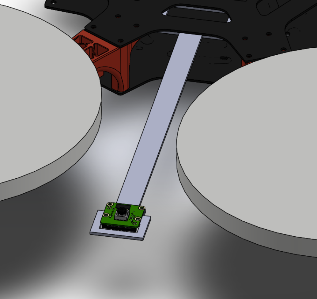
Camera Attachment Arm
Miscellaneous Tasks:
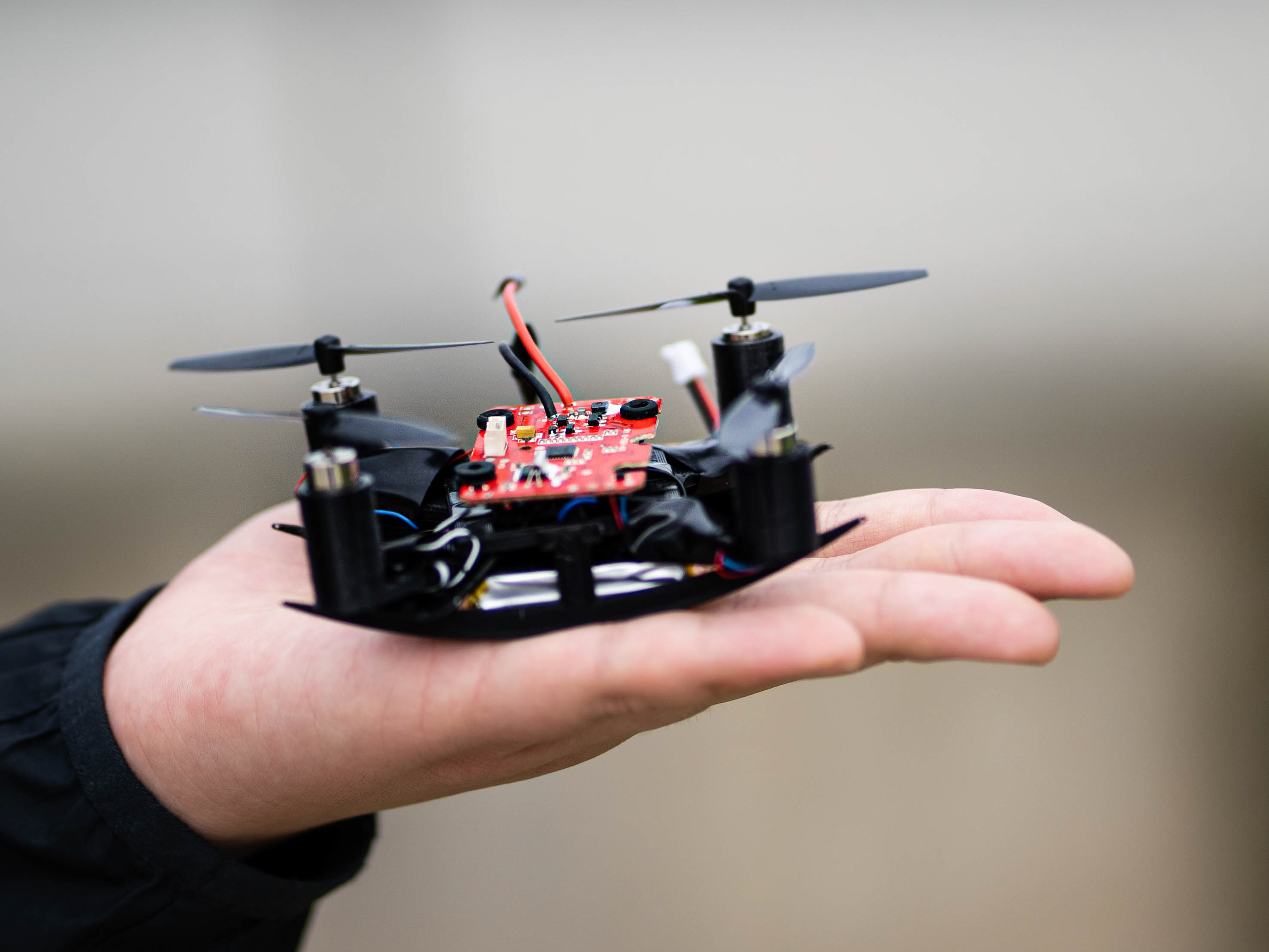
- Designed preliminary raspberry-based camera attachment arm to individual drones for the Computer Vision Team and the Docking Team.
- Planned build day for 4 F550 drone kits with pitched motor modifications.
Outcomes
- Successfully developed a mechanical system capable of supporting infinite flight.
- Project completed without final autonomous flight software due to the entire Controls Team graduating.
- If given more resources, AVIATA assembly, including full docking capabilities, would be first tested in a controlled environment (ex. an indoors gym), then move outdoors in a real environment with a mock task (ex. deliver payload to location).
Links
AVIATA Blogs: https://uas.seas.ucla.edu/aviata/blog.html
GitHub page: https://github.com/uas-at-ucla/aviata
USRC Tech Talk Recording: https://youtu.be/Udes0axZz5s
2021 TACP USRC Poster Presentation: https://youtu.be/c2nyjCBQSm8
UAS at UCLA website: https://uas.seas.ucla.edu
NASA USRC website: https://nari.arc.nasa.gov/usrc